LCD
Tech Research Project // October 17, 2002
Dennis Crowley, Vivian Lin, Ayad Alkadhi
[zoom in]
Ingredients
1 Emerging Display 16 x 4 LCD panel, 12 Pin (#ED10020TRU9511)
1 Oprtex DMC20434 16 x 4 LCD panel
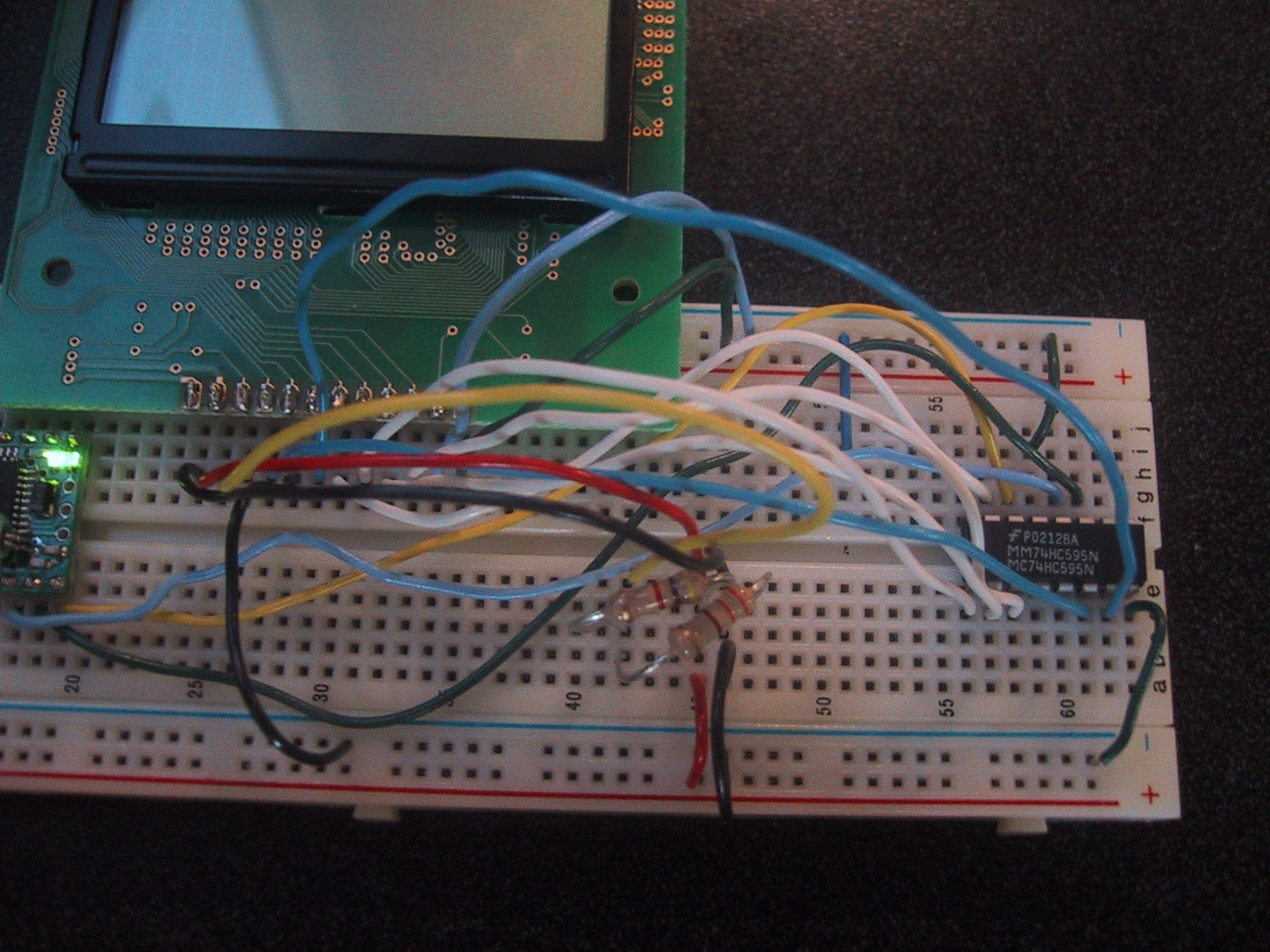
1 74HC595 Serial Shift Register (16 Pin)
1 330 Ohm resistor
2 4.7K resistor
Directions
1. Connect 3 pins from the BX24 to shift register
2. Connect power/ground to shift register (4 pins total)
3. Connect shift register to LCD (10 pins)
4. Connect LCD to power/ground (4 pins)
TroubleShooting
1. Handwritten instructions from 3rd party vendors
Knowing that the site we ordered the LCD from was a little homebrew-ish, we should have expected that the instructions
would be the same. When the kit arrived, it came with 3 pages of typed directions/notes and a hand-drawn schematic.
It was difficult looking at a poor photocopy of someone else's hand written schematic and trying to figure out
what was going on (especially with all the nuances involved with hooking up the LCD), so to anyone going forward with this
project, know what you're getting yourself into. (Sidenote: the guy we ordered the LCDs from was a great help. Every time
we encountered a problem, we fired off an email and received a reply in a matter of hours).
2. Lacking a strong connection btw LCD and board due to lack of sodering
When we first got started, we were so protective of our LCDs that we didn't want to attempt to soder wires to the
12 pins on the LCD's board. Instead we sodered wires to pins and stuck the pins into the LCD board. While this may
look like a good idea, it actually cost us a lot of time in since even though the pins looked like they were firmly
connected, some weren't making a solid connection. We didn't fully get the LCD to work until we finally broke down and sodered the pins onto the board.
3. Missing resistor problem (due to hard to read instructions)
This comes back to the hand-drawn instructions again. The shift resistor has a pin that looks (and who's description
reads) similar to the "reset" pin on the BX. The illustration showed a 4.7K resistor connected to ground from the reset
pin, but we figured this was only if we really needed to, you guessed it, reset the shift register. Thus, while we had
everything else on the board wire properly, we never really tried adding the reset-resistor resulting in us wasting a lot
of time trying to debug other things that didn't need to be debugged. It wasn't until we broke down and emailed the guy who sold us the LCD before his reply straightened things out for us and the LCD magically started working.
4. Overlooking small things (power supply, wrong cables, etc.)
I'm sure this happens with every project, but the more fiddling we did with wires/setup the more we started to overlook
simple problems. In our constant re-wiring we would occasionally accidently disconnect a wire from power or groud. These
things easily went overlooked and also caused us spend a lot of time debugging things that didn't need to be debug.
5. LCD display was adding extra spaces (due to even/odd lines, 16 x 20 line display)
This was the last of our glitches. Whenever we would send text to the 3rd and/or 4th lines of the LCD, the string
would was prepended by four blank spaces. It wasn't until later that we realized that the code that was supplied with the 16 x 4 LCD display is actually meant for a 20 x 4 display. The LCD handles the four lines on the display as two distinct lines (e.g. lines 1 and 3 are one line while lines 2 and 4 the other line), and the four spaces were the "blank
spaces" that the LCD thought belonged on line 1 or line 2 (20 - 16 = 4 = four blnak spaces). We finally figured out to
adjust the code that drives the LCD characters and removed the 4 spaces. After that, everything worked perfectly.
How it Works
The fortune cookie app is actually pretty simple. Each of the eight places to hide a fortune is connected to a simple
switch (two wires, one connected to a BX and one into ground) - the cookie starts off with all the switches in the "on" (getPin = 1) postion and as the flap hiding the fortune is lifted, the switch is turned "off" (getPin = 0). The code
features a loop that is constantly looking for a switch to, er, switch from on to off. When this event occurs, the
appropriate fortune is sent to the LCD screen.
Source Code
BasicX code that drives the fortunes
LCD functions (provided by the manufacturer)
Resources
The LCD dealer, phanderson.com
LCD overview from How Thing Work
Overview on shift registers from a former ITP student